Template Information

Trang

Chủ đề

BSP (44) Device Drivers (43) WinCE (38) WINDOWS DRIVER (19) Linux Device Drivers (18) ARM (17) Android tools and tips (17) DRIVER FILES (16) Windows Device Driver (16) AUDIO DRIVER (12) 8051 (8) OMAP (7) PRINTER DRIVER FILES (7) C Programming (6) ASUS MOTHERBOARD (5) Interfacing (5) NETWORK ADAPTER (5) VIDEO DRIVER (5) CANON (3) Device Driver Downloads (3) MOBILE PHONE (3) Asus Driver (2) EPSON (2) Epson Printer Driver (2) HP LAPTOP DRIVER (2) LAPTOP DRIVER FILES (2) Logitech Driver (2) NETWORK ADAPTOR (2) OMAP 4430 (2) drivers download (2) ACER (1) ACER TABLET (1) ALL IN ONE DRIVER (1) Acer Aspire 5738 Drivers (1) Analog-to-Digital (1) Asus Drivers (1) Asus Motherboard Drivers (1) Chip Architecture (1) DELL (1) Dell D610 Drivers (1) Dell Drivers (1) Device Drivers Download (1) Device drivers interview questions (1) Display Driver (1) Drivers Download for Windows 7 (1) EEPROMs (1) Free Asus Motherboard Drivers (1) Free Drivers Download for Windows 7 (1) GRAPHIC DRIVER (1) HP Driver (1) Hardware (1) Intel Drivers (1) Intel P35 (1) Intel P35 chipset drivers (1) I²C (1) LAPTOP SERVICE MANUAL (1) LCD (1) Logitech Mouse Driver (1) Logitech webcam driver (1) MODEM DRIVER (1) Motherboard Drivers for Windows 7 (1) PARALLEL PORT (1) Pc Driver (1) RTOS (1) Real Time Clock (1) Sensors (1) USB CABLE DRIVER (1) WEBCAM DRIVER (1) WIRELESS ADAPTOR (1) Windows 7 Drivers (1) Windows Mobile (1) acer driver (1) acer driver downloads (1) acer laptop driver (1) chipset drivers (1) network card driver (1) network driver download (1) sdcc (1)

Bài viết ngẫu nhiên

Xem phim HD Online

Số lượt views

Network Card Driver Download – Best way to End Internet Issues

Chủ Nhật, 25 tháng 9, 2011 / 23:50


So, you are again using your friend’s PC for accessing the internet? Your system denies to get connected to the internet and you waste a whole lot of your time over searching the real reason behind it, seems serious right? So now being fed up you’ve started using your friend’s PC. Well, it looks quite clear that your actual trouble is with your network card.

Did you try checking your network card driver? It appears that your card driver is troubling you and this is why you’re facing such issues. The best way to deal with it is time to time network card driver download. You might be thinking how can this prove helpful, right? 

Well, let’s take the example of regular health check up, so you go for your regular check up schedule, don’t you? This reduces the possibility of falling ill as all possible symptoms come to notice on time and with precaution, you get saved, right. Similarly, whenever you go for a fresh download, you remove the older driver, if the older version has already got any trouble or is about to get any trouble, you solve it before it has taken a more complicated form.

So, if you’re going through a tough time with the internet connectivity, best is to go for a network card driver download. It is normal to think how the entire card can get into trouble because of a mere driver, but the thing is that the driver is not a mere thing, even when it appears to be. The drivers work from behind, this make us think that they hardly do anything.

But if they go missing from your system, the devices corresponding to them get trouble in working. Now when your network card driver will stop working or develop some working issues, your network card will show connectivity issues and you’ll not be able to access the internet. This will happen because the driver creates a kind of association between your card and the system and when it won’t work anymore, there won’t be any more association leading to it inability to work.

Now to solve this you’ll simply have to remove the older driver and go for a fresh installation. But the trouble is that your disc may have an outdated version of the driver, which won’t prove helpful, at such times undergoing network card driver download proves most helpful as you get the latest version of the driver and can look forward to it every time you get into a trouble.

So, stop wasting your time, now when you’re accessing internet from your friend’s PC, simply download the driver and take the back up and finally install it on your system. This isn’t very difficult, simply hit any reliable looking site that offers network card driver download, and have the downloading done.
Chủ Nhật, 25 tháng 9, 2011 23:50 Đọc tiếp >>

Booting Windows CE from Hard disk using PC BIOS

Thứ Ba, 20 tháng 9, 2011 / 10:26

Introduction
This document explains the build process for the Windows CE BIOS bootloader. The Windows CE image (NK.BIN) has to be loaded by the BIOS directly from the Hard disk, without any user intervention. The process should be like the way how a normal PC BIOS loads the OS from hard disk.

This BIOS boot loader component is responsible loading the Windows CE OS from the Hard disk and placing on the RAM and pass on control to it. This contains the Boot level file system support and reads the Windows CE image from the OS partition.

This document is derived out of Build instructions that are devised by e-con engineers during the development stage and also the compilation of mails MSDN Embedded newsgroups.
 
Scope
The scope of this document is limited to the steps involved in the building of the BIOS bootloader and the modifications done in the existing source code given by the Microsoft. The BIOS boot loader code is a standard X86 boot code and the changes done are very specific to the Buffer size.
 
Intended Audience
This document is intended for embedded engineers who are involved in the development of Windows CE on PC platforms such as CEPC or any other PC-compliant platforms which has standard PC BIOS and hard disk.
 
Build Environment
The build environment is Windows CE 5.0 Platform Builder. We have used both normal PC as a CEPC platform and x86 based PC-compliant target board from ICOP. The build instructions are tested on both the platforms.
Building the BIOS Bootloader (BLDR)
  • Start the Windows CE 5.0 Command Prompt
  • Go to Public\common\oak\misc
  • Run the WinCE.bat file with the target cpu type, project name and platform name. Without this environment variables won’t be set and nothing can be built with the command line window.
    • For our case, we have a cepctest project of platform type CEPC.
    • Give the command as follows
      • wince.bat x86 cepctest CEPC
    • Please note that these arguments are case sensitive.
    • This will set up the environment variables for us to start the build process
  • Then go to PUBLIC\COMMON\OAK\CSP\X86\BIOSLOADER\LOADER directory.
  • Open the fat.h file and change the READ_BUFFER_LENGTH_MAX from 0x4000 to 0x3000
  • Then give build –c on the command line. This should build bldr file in the same directory. This should be of size 20kB
  • In case if the build fails, it might be because iniparse.lib is not built. If so go to PUBLIC\COMMON\OAK\CSP\X86\BIOSLOADER\INIPARSER directory and build that first. Then build the loader directory.
 
Making the Setup Disk
  • WE have to create the setup disk. This disk shall contain all the necessary stuff to make a hard disk partition bootable.
  • Go to the PUBLIC\COMMON\OAK\CSP\X86\BIOSLOADER\DISKIMAGES directory. Put a floppy on the A: drive and double click the SETUPDISK.144.
    • Before that you should have registered the .144 file. To do that, go to <INSTALL_PARTITION>:\Program Files\Windows CE Platform Builder\5.00\CEPB\UTILITIES. Run the file websetup.exe. This needs to be run only once. This will register the handler for the .144 files.
  • Once the setupdisk.144 runs successfully, you have your setup floppy disk ready. Open this floppy disk and replace BLDR with the BLDR that we had built with READ_BUFFER_LENGTH_MAX as 0x3000.
  • This floppy itself contains a file called boot.ini which specifies the some important parameters. Edit this file as given below:
    • Editing Boot.ini file
      • Change the DisplayWidth, DisplayHeight and DisplayDepth to suit your requirements. For our board we set them as 1024, 768, 16
      • Change the line BinFile=eboot.bix to BinFile=nk.bin. The original one would be eboot.bix. Basically this states which OS image to use. We specify it as nk.bin and we keep a working WinCE OS image nk.bin in the hard disk.
      • Similarly set BakBinFile=eboot.bix
  • Copy this boot.ini file to setupdisk or keep it in another floppy. We have to copy this file also to the hard disk.
  • Now our setup disk is ready.
Setting the Environment and Making the bootable hard disk
  • Now start your target board or CEPC with the setupdisk floppy that we had created just now.
  • Use fdisk to create partition the hard disk or CF or DiskOnChip from which you want to boot your Windows CE automatically.
  • Ensure that the Primary partition is less than 512MB. There are lots of discussions on the Newsgroups on this restriction. For our case, we keep the primary partition to 32MB, just to hold the nk.bin and registry. And set this primary partition as Active, again using fdisk. Let us call this primary partition as C:
  • Create and configure other partitions for your usage. For our case we create one more partition of remaining 220 MB.
  • During FORMAT steps to follow
    • Delete the present C: promt by selecting 3 in the choice given after u run fdisk
    • Then select 1 to create partition in that select I for primary and for 32MB
    • Make that one active by selecting 2 choice this will be u r C drive
    • Then create another extended partition for remaining memory in extended memory and that will be stored as D drive after that make that one by selecting choice 3
    • Then format the C and D drive .Otherwise u will get error if u run mkdisk
  • Once partitioning is done, run the mkdisk command with the argument C: i.e. as mkdisk C:
  • This will copy the bootsect.img and the bldr files from the floppy to the hard disk, in the proper sectors of the hard disk. Basically it is not simply copy, but a different operation. The bootsect.img is placed in the first sector, i.e., track zero, head zero, sector one of the hard disk or called as MBR. And another restriction is that BLDR is placed in contiguous sectors.
    • A small digression here. At power-on, the BIOS code performs POST.
    • The BIOS seeks out the boot disk and on a fixed disk, loads the first sector (the master boot record - MBR) on to RAM at 0000:7C00 (Real mode) and jumps to it A typical MBR code reads the available Operating systems and displays them to the user. It will load the corresponding loader for the OS selected by the user. This is known as two-stage bootloader. An example of that is GRUB.
    • In our case, we don’t have special MBR code that reads the available Operating Systems and displays to the user so that he can select any one. Our bootsect.img just looks for the bldr and loads the bldr to RAM and passes the control to it. In this process, so many transfer of code inside the RAM locations will take place.
    • This boot sector code is the first filesystem-specific bit of code and it's job is to locate, load, and bootstrap the OS (or in our case, the bldr).
    • This bootsector code only displays the string “Microsoft Windows CE BIOS Bootloader” on the screen.
    • If the bldr is not found, then it displays the error message “Unable to load BLDR!”
  • After this bldr code takes over and configures the screen, initiates the OS loading process. It also configures the debug serial port and sends out the debug messages at 38400 baud, no parity, 8bits of data and one stop bit. It then locates the nk.bin and loads the nk.bin and gives the control to it… and we get our Windows CE desktop!!! Before that we should have our working nk.bin on the boot partition. That is described next.
  • Once mkdisk is done, if you run dir /ash C: you can see the bldr on the C: drive
  • Now copy the boot.ini (which is edited by us), splash.bmx and eboot.bix files from the setupdisk floppy to C:
  • Now we are all set except the actual Windows CE image nk.bin
Finally putting it all together
  • Now we are done with all the necessary stuff. We need to have a working nk.bin to boot from.
  • Another small digression here. This nk.bin will be placed in the boot partition and will be loaded by the bldr. This nk.bin should already have been tested. The important thing to note here is that this nk.bin should be shipping version. That is, this should be a release version with no debugging support. To make this go to Platform->Settings menu on the Windows CE Platform Builder (with your platform workspace loaded). Go to the Build Options tab and uncheck all the check boxes. Build the image and this image is a shipping version of nk.bin
  • Now somehow copy this nk.bin to the C drive. In our environment we use the following technique
    • Copying the nk.bin
    • We create a test platform with hard disk, Ethernet and FTP enabled. We build the platform and we get the WinCE image. Let us call this as nkloader.bin
    • We use the CEPCBoot floppy and boot the target machine (or CEPC) and using Ethernet, we load our nkloader.bin and run it
    • Now we connect to the target machine and copy our shipping version of nk.bin through FTP
    • We copy this actual shipping version of nk.bin from the FTP home directory (by default it is in /Temp) to the boot partition of the hard disk (i.e. C: in our Windows CE, this will “My Device/Hard disk”). And we are done with that. Our nk.bin is on the boot partition
  • Now we are complete. Remove the floppy. Configure the BIOS to use the hard disk as the default boot device and reboot the target (or CEPC)
  • You should see you nk.bin loading and enjoy your Windows CE on your target board booting out of hard disk directly!!!
 
Action Item and Conclusions
The above instructions are tested on a fresh installation of Windows CE Platform Builder. The next step is to have the custom boot logo and our own boot progress bar.

Thứ Ba, 20 tháng 9, 2011 10:26 Đọc tiếp >>

GPRS connectivity through dial up and Networking – Part II

Introduction
Windows Embedded CE provides GPRS communication through the cellcore architecture (Cellular TAPI service provider) and through the Telephony API (TAPI 2.0 Unimodem driver). Cellcore architecture is highly featured architecture and it expects the GSM modem with high capability. Unfortunately not all the modems support all the features expected by the cellcore architecture. Also highly featured modems are not preferred for some applications because of the hardware and software cost constraints. In these cases cellcore architecture is not preferred, instead applications can use Telephony API provided by Windows CE. Using TAPI is not straight forward and has limitations that need to be addressed. This article focuses on addressing these limitations.
Intended Audience
The Part 1 of the GPRS Connectivity article (Making GPRS connections in Windows CE 6.0) focused on establishing a DATA connection through GPRS using the dial-up networking.
The audience of that article raised a number of queries like
1. How to send an SMS when data connection is ON?
2. How to access the address book on the SIM or how to get the signal strength?
There is a single solution to all the above and similar questions. This document focuses on the solution and its implementation. This article would cater to a variety of audience including engineers, managers and wince enthusiasts who want to have parallel activities like signal strength detection, address book lookup, etc. to happen when the data connection is still ON.
Engineers who are just interested in just the data communication via dial up and networking via GPRS can read this article Making GPRS connections in Windows CE 6.0
Scope
The scope of this document is limited to the modems that support the CMUX protocol (part of the GSM07.10 standard).
Telephony API
Telephony API (TAPI 2.0) is developed and used to establish the data communication through the AT command based modems. Since the GSM modems are AT command based modems, TAPI is used for GPRS data communication. Using RAS APIs GPRS connection could be established.
Figure 1 - TAPI Architecture
(Click image to enlarge)
Telephony API uses the universal modem driver (TSP for AT Command modem) to establish the GPRS connection. The unimodem uses the serial port driver to access the modem. Please refer the article,Making GPRS connections in Windows CE 6.0 to know more about the GPRS data communication through the Telephony API.
Limitations of unimodem architecture
In general once the GPRS communication is established, the corresponding serial port becomes busy and is not accessible by the other processes and it is dedicated to the unimodem driver. This is a great barrier to access some simple features of the GSM modem like getting the signal strength, accessing the phone book etc., unless there is a dedicated port for accessing these features. Unfortunately not all modems support the dual serial port to access the GPRS and the other modem features simultaneously. Also increasing one more serial port increases the hardware overhead. The following section will explain the architecture of modern day GPRS modems and also how to use the internal multiplexer provided by the modem to resolve this limitation.
Architecture of contemporary GSM/GPRS modems
 
Figure 2 GSM Modem Multiplexer
Figure 2 illustrates the architecture of a GSM/GPRS modem. As shown above each GPRS/GSM modem has a internal multiplexer which takes the commands from the serial port and then internally passes on to the respective channels like circuit switched data, packet switched data, status/control, phone book access,etc. Basically, the client application communicates with the MUX (though this involves several steps as indicated below). Most of the contemporary multiplexers are designed to support CMUX protocol(part of the GSM07.10 standard) which operates between the GSM/GPRS modem and a Terminal equipment(TE ) and allows a number of simultaneous sessions(channels) over a normal serial asynchronous interface. Each session(channel) consists of a stream of bytes transferring various kinds of data like voice, fax, data, SMS, CBS, phonebook maintenance, battery status, GPRS, USSD etc. This permits SMS and CBS to be transferred to a TE when a data connection is in progress. Many other combinations are possible including digital voice. It is, for instance, possible to transfer digital voice in combination with SMS. Each channel has its own buffer management and flow control mechanism. The CMUX protocol supports up to 64 channels as illustrated above.
 
Windows Embedded CE 6.0 GSM 7.10 MUX driver
Windows Embedded CE 6.0 supports GSM0710 multiplexer driver as a component in the cellcore architecture and this multiplexer driver is a separable component from the cellcore architecture. Depending on the modem’s capability the channels will be available to be accessed as a virtual serial port to the applications. Normally GSM modem will not be in the multiplexer mode. GSM0710 multiplexer driver will send the AT+CMUX command to enable the multiplexer mode and following that the driver will send SABM frame for requesting the channel. The first channel is the control channel and the remaining channels are the communication channels. These communication channels are exposed as virtual com ports. Figure 3 shows the interface between the multiplexer enabled GSM modem with the windows CE Device.
Figure 3 - GSM Modem interface with Windows CE multiplexer driver
Integrating the unimodem driver with MUX
An approach to perform the multiple simultaneous operations on GSM modem as described above, is would be to use the virtual serial ports exposed by the MUX driver. There are two ways to do the GPRS data communication. The first way is porting the unimodem driver to establish the GPRS data communication through virtual serial port and the other way is writing own TSPI driver that will do the same. For both the cases engineers must have a good understanding on the GSM.07.10 windows Embedded CE 6.0 driver as well as an idea of how the TSPI driver works.
Developing proprietary TSPI driver
Sample TSPI driver is provided in the “wince600/public/common /oak/ drivers /SAMPTSPI” directory. Using this driver proprietary TSPI driver can be developed. The issue is the development time and the testing time duration is high.
Porting the Unimodem driver
Figure 4 illustrates how the unimodem driver can be integrated with the MUX driver. The unimodem driver needs to be ported since the MUX driver may not be supporting some IOCTL calls the unimodem might be expecting. Porting the unimodem driver won’t take time, since the driver is already developed and tested.
Expected Issues
The GSM.7.10 multiplexer driver provides the virtual serial ports. This multiplexer driver is implemented as a normal serial port driver and it has to handle lot of IOCTL calls from the unimodem driver. The unimodem would be expecting a serial driver whereas there is a multiplexer driver which is taking these calls. These IOCTLs are accessed through the standard serial port driver APIs. Unfortunately multiplexer driver doesn’t support all these IOCTL calls. For example, consider the “PurgeComm()” API. This function can discard all characters from the output or input buffer of a specified communications resource. But this API’s corresponding IOCTL is not implemented in the multiplexer driver. But the normal serial port driver will support this call. Hence some function call backs in unimodem driver have to be removed or some API calls have to be implemented in the multiplexer driver.
Figure 4 - TAPI on Multiplexer
Benefits
  • Simultaneous data connection, usage and access of other features like SMS, address book, etc.
  • Possible to write custom application with seamless voice and data communication.
  • The voice communication support on cellcore architecture is in Windows CE professional license.
    Writing custom application for voice communication and using the unimodem for data communication
    will be cost effective.
Conclusion
Thus a multiplexer enabled GPRS modem can be used to send both data as well as used to send SMS, access phone book, etc.


Thứ Ba, 20 tháng 9, 2011 10:22 Đọc tiếp >>

Windows CE 6.0 GPRS connectivity through dial-up networking

Introduction
Windows CE provides two ways to obtain connectivity with a GPRS modem: by using the "cell core" function, and using "dial-up networking." Because most GPRS modems are not available with support for the Radio Interface Layer (RIL) driver required for the former of these options, dial-up networking is often what is required.

This document explains how GPRS modems can be used for dial-up networking on Windows CE 6.0-based devices. It also provides solutions to typical problems that may arise when implementing this approach.
GPRS connectivity
Cellular systems combined with GPRS are often described as 2.5G -- that is, a technology between the second and third generations of mobile telephony. GPRS provides moderate speed data transfer, by employing unused TDMA channels in, for example, the GSM system. GPRS, based on packet switching methods, is a successor to earlier circuit switch data connectivity techniques. It can provide uplink and downlink speeds of up to 50 Kbits/sec. GPRS, in turn, has more recently been supplanted by EDGE, UMTS, and other high-speed transfer technologies that offer speeds on the order of megabits per second. However, in several developing countries, such as India, GPRS is still the main method used for data transfer on mobile devices.
GPRS modems and the need for RIL
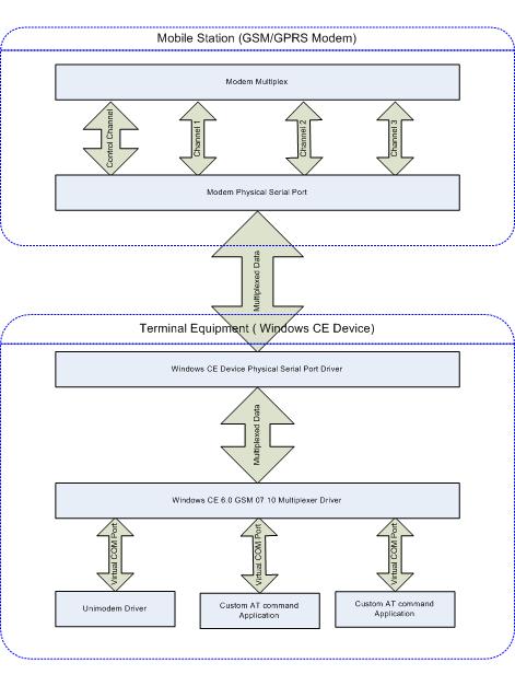
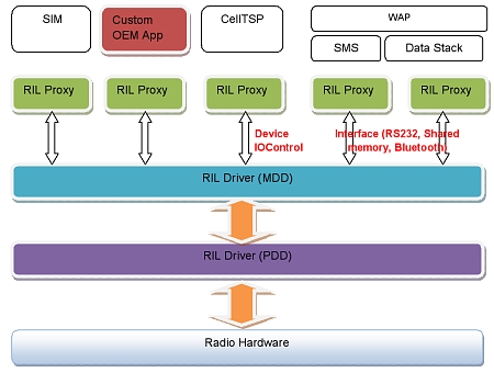
Modems have recently become quite complex, particularly due to the need for an internal multiplexer along with the device drivers required to support it. This is necessary because today's cellular modems must support multiple interfaces, such as USB, shared memory, UARTs, etc. Even when the modem is using a simple UART interface, if the interface has been configured for data, there is no way for an AT command to be passed through the interface to get status etc. There are, for example, modems that require the data connection to be disconnected and the voice connection to be started, in order to initiate voice communications in GPRS mode. Recently, modems have tended to expose multiple ports for each service, in order to support the use of voice, SMS, and data simultaneously. Internally, the modem has a multiplexer to handle this. To abstract the developer from all this complexity of handling AT commands for multiplexing etc, Microsoft has introduced Radio Interface Layer - RIL drivers that interact with the radio hardware.
RIL provides proxy devices or COM ports to handle each device inside the modem. Figure 1 shows how RIL exposes proxy devices to the application developer. This type of handling becomes a necessity when the user needs voice, SMS, and data to be done simultaneously and the modem supports such capabilities. An RIL driver in principle could support a proxy or virtual COM ports for voice, data, and SMS; in practice, however, an RIL driver might only support a single COM port interface with the modem.
Figure 1: How RIL exposes proxy devices to the application developer
RIL vs dial-up networking
Some mobile Windows CE devices, such as hand-held POS (point of sale) terminals, do not require voice or SMS connectivity; instead, they simply require a data connection to obtain data from a remote server or store it to a remote server over the cellular network. In the event that a mobile terminal requires GPRS connectivity, there are two ways to manage the modem interface:
  • Connecting through RIL
  • Connecting through dial-up networking
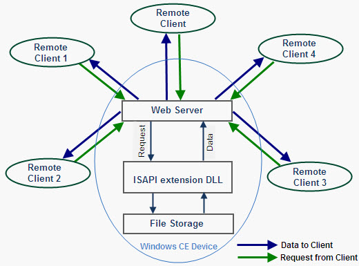
Since most GPRS modems do not come with RIL drivers, it is often necessary to utilize dial-up networking. If the modems are used only for data -- and not for voice, data, and SMS -- or to get status repeatedly about the connection etc., then it is better to go with the standard dial-up networking feature of Windows CE. This is because the application only needs a single serial port connection, and does not require the use of special modem features.
Figure 2: Connecting through dial-up networking
(Click image to enlarge)
This article analyzes the problems and steps involved in establishing a GPRS connection using Windows CE's standard modem support for dial-up networking. The procedure to accomplish this consists of four steps:
  • Source code changes
  • Registry settings
  • Build options and OS design component selection
  • Run time steps to connect the GPRS
Source Code Changes
The GPRS connection requires a driver component in the Windows CE layer. The Universal Modem (Unimodem) is the standard 19200 baud rate modem driver used for connecting to the GPRS modem through a serial port. This driver conforms to the PC’s standard 19.2Kbps serial modem driver. The Unimodem driver supports GSM modems, which support "Hayes Compatible" modem "AT commands" and data transfers.
The Unimodem driver is part of the Windows CE driver package; the source code of the Unimodem driver is also available. This driver should work as provided without any changes, and should support any serial 56Kbps dialup telephone modem connected to the serial port. However, when a GPRS device is connected to the serial port, the Unimodem driver does not appear to support the new GPRS modem in the same way has supported dialup modems in the past.
A timing problem arises when using GPRS. This is because GSM/GPRS modem command processing is slower than what is provided by normal PSTN (landline) dialup modems, resulting in longer response times. Consequently, a command response timeout may occur during the initialization sequence, and the connection may therefore not be established.
A watch-dog timer thread running in the Unimodem driver maintains the timing counter. The driver expects an "OK" response before the watch-dog timer times out. Unfortunately, however, the timer times out in the case of GPRS.
So, when an AT command is sent during the connection phase, the Unimodem driver times out the transaction well before the expected response (OK) is received. To resolve the issue, following changes has to be made to the Unimodem driver.
Change the value of the INIT_WATCHDOG_TIMEOUT #define parameter to 10 times its original value.
Registry settings and Modifications
The registry settings pertaining to the GPRS connection have to be set properly in order to get the connection established successfully. The registry keys of importance are discussed in this section.
The poor response time of the GPRS modem creates problems with the watchdog timer in the Unimodem driver, as discussed above. During some timeouts the modem is reset by the Unimodem driver. This can be overridden using the registry settings.
In the platform.reg file the entry under the \Unimodem\Settings registry key, "Reset" = "ATZ", would result in the modem being reset. To disable this and protect the modem to preserve the previous modem settings, the following setting has to be used: "Reset" = "AT". Here is a snippet from the platform.reg file:
;**********************Overriding Unimodem settings***********************
[HKEY_LOCAL_MACHINE\Drivers\Unimodem\Init]
"1"="AT<cr>"
"2"="ATE0V1&C1&D2<cr>"
[HKEY_LOCAL_MACHINE\Drivers\Unimodem\Settings]
"Prefix"="AT"
"Terminator"="<cr>"
"DialPrefix"="D"
"DialSuffix"=";"
"Pulse"="P"
"Tone"="T"
"Blind_Off"="X4"
"Blind_On"="X3"
"CmdSendDelay"="500"
"CallSetupFailTimeout"="ATS7=<#><cr>"
"Reset"="AT<cr>"
[HKEY_LOCAL_MACHINE\Drivers\Unimodem\Config]
"CallSetupFailTimer"=dword:B4
Another problem that the registry settings pose pertains to the telephone dialing number and related details.
When the components are chosen, the default registry settings will be initialized with country code and area code values that most likely won't match your application's requirements. This causes an improper number to be dialed. Obviously, the registry settings have to be modified to solve this problem. These registry settings override the default registry settings, and will accept only the local number. For GPRS, *number# will be used to establish the connection.
In the platform.reg file, care must be taken to ensure that the correct numbers are entered. Here is an example snippet of what is contained in platform.reg:
;************************Overriding Dialing Settings***********************
[HKEY_CURRENT_USER\ControlPanel\Dial]
; What is Location ID (value name) for the current location
"CurrentLoc"=dword:0
; What is the next permanent location ID to be used when creating a new entry
"HighLocID"=dword:2
;Default Location settings -- need to be localized
[HKEY_CURRENT_USER\ControlPanel\Dial\Locations]
; Each MultiSz location (value name = PermLocationID" has :
; LocationName, LocalFmt, LdFmt, IntntlFmt, AreaCode, CwCode, CountryCode, & Options
"0"=multi_sz: "Work",
"G",
"G",
"G",
"425",
" ",
"1",
"0"
"1"=multi_sz: "Home",
"G",
"1FG",
"011,EFG",
"425",
" ",
"1",
"0"
;*****************************************************************
Build Options and OS Design Component selection
There are no special build options required, for building the "GPRS Connection through Dial Up and networking." However, the following components have to be added in order to get the "GPRS Connection through Dial Up and networking" to build properly:
  • Communication services and Networking->Networking Wide Area Network (WAN)
  • Dial Up Networking(RAS/PPP) (Including all the sub component)
  • Telephony API(TAPI 2.0) (Including all the sub component)
Run Time steps to connect the GPRS through the Dial Up and networking
This section details the steps involved in connecting to GPRS with Windows CE's dial-up networking function. Screenshots are provided, to illustrate the process.
Since all the Dialing options are set in the registry settings, there is not much need to change the Dialing properties in the Dialing wizard that pops up when clicked on the Properties of the connection.
Figure 3 shows the settings of the Dialing properties:
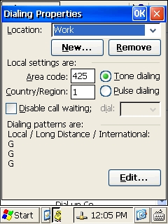
Figure 3) Dialing Properties
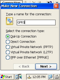
Go to the control panel --> Network and Dial up wizard. Click "Make New Connection."
Type the name of the connection; for example, "GPRS." Select the Connection type as the Dialup connection. Click "next" to continue. Figure 4 shows the new connection wizard:
Figure 4) Make New Connection
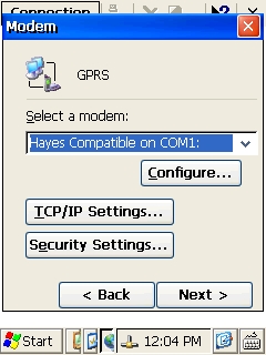
Select “Hayes compatible on COM1” as a modem diver in the “select a modem” option and click “Configure” button. Fig 5) shows this step.
Figure 5) Select a modem
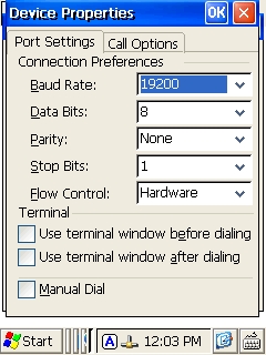
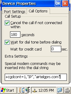
The "Device Properties" dialog box will open. Leave the port settings tab as it is, and click the "call options" tab. Figure 6 shows these tabs.
Figure 6) Device properties
In the "call option" add the special initialization command in the text box as shown in Figure 7. The original command is AT+CGDCONT=1,"IP","airtelgprs.com". This AT command may differ from one service provider to another, so be sure to check with the applicable service provider for the correct command setting.
 
Figure 7) call Options
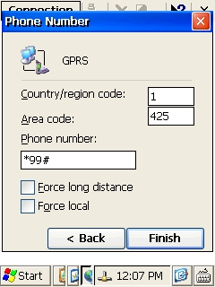
Click "Next" and enter the phone number, *99#, in the phone number dialog box. Figure 8 shows the phone number dialog box. Click the "finish" button.
Figure 8) Phone Number
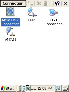
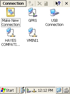
The new "GPRS Connection" appears in the network and connection wizard. Figure 9 shows the new connection:
 
Figure 9) Network Connections
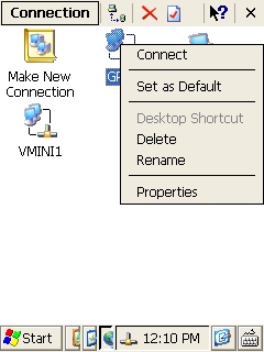
Right click the "GPRS icon" and click the "Connect" for connecting to GPRS. Figure 10 depicts this step, and Figure 11 shows that the device has connected to the GPRS network.
Figure 10) Connect to GPRS.
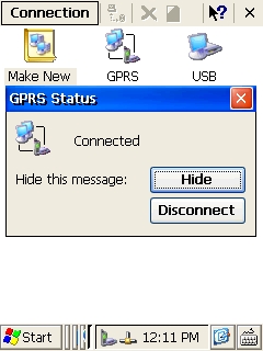
Figure 11) Device has connected to the GPRS network
Conclusion
The Windows CE dial-up networking component and Unimodem driver can be efficiently used to include support for transferring data over GPRS modems in Windows CE 6.0-based systems and devices.


Thứ Ba, 20 tháng 9, 2011 10:15 Đọc tiếp >>

Operating CF in UDMA Mode in WinCE using IDE interface through IDE to CF adapter

Abstract
In many Wince devices Compact Flash (CF) cards are used through IDE (ATA) interface by using IDE to CF adapter. CF cards are available in PIO mode and Ultra DMA mode (UDMA). We have seen many enquiries in the newsgroups and mailing lists about the CF card not working or the Ultra DMA mode not working in Windows CE. Sometimes the problems are there in the IDE to CF adapter card or in the software driver. This article addresses both of these issues and helps the developers how simple to make work of CF in Ultra DMA mode using IDE to CF adapter.
CF Card Revisions
Compact Flash defines a physical interface which is smaller but electrically identical to the ATA interface. That is, it appears to the host device as if it were a hard disk. The CF device contains an ATA controller. There are different revisions of CF cards available. Revision 2.0, revision 3.0 and revision 4.0 will work in Ultra DMA16 (Speed 16MB/s), Ultra DMA66 (Speed 66MB/s) and Ultra DMA133 (Speed 133MB/s) mode respectively. PIO mode supports up to 25 MB/s. All the revisions have backward capability.
CF Card Device Information
Each CF card revision details, sectors, cylinders, PIO mode support, DMA support details are available in the device information memory. This information is read using “Identify Device” Command. The following is the register that defines the PIO and DMA specifications.
Word Address Default Value Data Field
 49  0h  Capabilities
 53  000Xh  Field Validity
 64  00XXh  Advanced PIO Modes Supported
 88  XXXXh  Ultra DMA (UDMA) mode supported and selected
In the Word 49 – Bit 9 and 8:
Bit 9: LBA supported

Bit 9 shall be set to 1, indicating that this Compact Flash Storage Card supports LBA mode addressing. CF devices shall support LBA addressing.
Bit 8: DMA Supported
If bit 8 is set to 1 then Read DMA and Write DMA commands are supported.
If bit 8 is set to 0, then Read DMA and Write DMA commands are not supported.
Word 64:
Bits 7 through 2 are reserved.
Bit 0, if set to one, indicates that the Compact Flash Storage Card supports PIO mode 3.
Bit 1, if set to one, indicates that the Compact Flash Storage Card supports PIO mode 4.
If bit 1 of word 53 is set to 1, the values in words 64 through 70 are valid. If this bit is cleared to 0, the values reported in words 64-70 are not valid. Any Compact Flash Storage Card that supports PIO mode 3 or above shall set bit 1 of word 53 to one and support the fields contained in words 64 through 70.
Word 88:
Bit 15: Reserved.
Bit 14: 1 = Ultra DMA mode 6 is selected 0 = Ultra DMA mode 6 is not selected.
Bit 13: 1 = Ultra DMA mode 5 is selected 0 = Ultra DMA mode 5 is not selected.
Bit 12: 1 = Ultra DMA mode 4 is selected 0 = Ultra DMA mode 4 is not selected.
Bit 11: 1 = Ultra DMA mode 3 is selected 0 = Ultra DMA mode 3 is not selected.
Bit 10: 1 = Ultra DMA mode 2 is selected 0 = Ultra DMA mode 2 is not selected.
Bit 9: 1 = Ultra DMA mode 1 is selected 0 = Ultra DMA mode 1 is not selected.
Bit 8: 1 = Ultra DMA mode 0 is selected 0 = Ultra DMA mode 0 is not selected.
Bit 7: Reserved.
Bit 6: 1 = Ultra DMA mode 6 and below are supported. Bits 0-5 shall be set to 1.
Bit 5: 1 = Ultra DMA mode 5 and below are supported. Bits 0-4 shall be set to 1.
Bit 4: 1 = Ultra DMA mode 4 and below are supported. Bits 0-3 shall be set to 1.
Bit 3: 1 = Ultra DMA mode 3 and below are supported, Bits 0-2 shall be set to 1.
Bit 2: 1 = Ultra DMA mode 2 and below are supported. Bits 0-1 shall be set to 1.
Bit 1: 1 = Ultra DMA mode 1 and below are supported. Bit 0 shall be set to 1.
Bit 0: 1 = Ultra DMA mode 0 is supported.
Bit 2 shall be set to 1 indicating that word 88 is valid and reflects the supported True IDE UDMA transfer modes:
From the above register it is possible to know the mode of transfer supported by the CF card.
CF and IDE Pins Layout
There are 50 pins in CF where as in IDE 40 pins so, it is important to check the pins mapping.
Pin CF Pins IDE to CF Adapter Pins Pin Type
 1  GND  -  -
 2  D03  -  I/0
 3  D04  -  I/0
 4  D05  -  I/0
 5  D06  D06  I/0
 6  D07  D07  I/0
 7  CS0  CS0  I
 8  A10  -  I
 9  -0E  ATASEL  I
 10  A09  -  I
 11  A08  -  I
 12  A07  -  I
 13  Vcc  Vcc  -
 14  A06  -  I
 15  A05  -  I
 16  A04  -  I
 17  A03  -  I
 18  A02  A02  I
 19  A01  A01  I
 20  A00  A00  I
 21  D00  D00  I/O
 22  D01  D01  I/O
 23  D02  D02  I/O
 24  WP  -  O
 25  0  GND  O
 26  0  GND  O
 27  D11  D11  I/O
 28  D12  D12  I/O
 29  D13  D13  I/O
 30  D14  D14  I/O
 31  D15  D15  I/O
 32  0  CS1  I
 33  -VS1  -  O
 34  -IORD  -IORD  I
 35  -IOWR  -IOWR  I
 36  -WE  -  I
 37  Ready  IRQ  O
 38  Vcc  -  -
 39  -CSEL  -CSEL  I
 40  -VS2  -  O
 41  RESET  RESET  I
 42  -WAIT  IOCHRDY  O
 43  -INPACK  DMARQ  O
 44  -REG  DMACK  I
 45  BVD2  -  O
 46  BVD1  DMA Detect  O
 47  D08  D08  I/O
 48  D09  -  I/O
 49  D10  -  I/O
 50  GND  GND  -
In many IDE to CF adapter, mapping of DMARQ and DMACK are not done. These adapters will support only PIO mode, irrespective of CF card type. UDMA supported CF cards will not work in Windows CE 5.0 and Windows CE 6.0 if these IDE to CF adapters are used. Only PIO mode supported CF cards will work using these IDE to CF adapters. DMA supported IDE to CF cards are also available.
Ultra DMA Hardware Requirement
  • Operation in Ultra DMA mode requires a crosstalk suppressing cable. The IDE to CF adapter shall have a grounded line between each signal line.
  • Series termination resistors are required for the pins IORD, IOWR, CS, A00, A01, A02, DMAC, DACK, D0 to D15 and IORDY on both the host (Board) and on the IDE to CF adapter cards for operation in any of the Ultra DMA modes.
Windows CE ATAPI driver
In many cases Ultra DMA (UDMA) supported CF cards are not working, this is due to the IDE to CF adapter and a small fix in software was introduced to make it work in PIO mode. Windows CE provides driver that works in PIO and UDMA mode. When the ATAPI driver loads, it will read the CF card device information. These information’s are used to decide in which mode (PIO or DMA) the ATAPI driver should load.
If the device information states that CF card supports UDMA mode, ATAPI driver starts issuing the DMA commands. ATAPI driver will fail if the IDE to CF adapter doesn’t support the DMA pins and should start trying the PIO mode. Normally it doesn’t and hence the driver stops working. To make the driver work in PIO mode, the following fix was introduced to indicate the driver that the CF card supports only PIO so that the ATAPI driver will work in PIO mode.
m_Id.DoubleWordIo = 0;
m_Id.Capabilities &= (~0x0100);
m_Id.SingleDmaModesSupported = 0;
m_Id.SingleDmaTransferActive = 0;
m_Id.MultiDmaModesSupported = 0;
m_Id.MultiDmaTransferActive = 0;
m_Id.TranslationFieldsValid &= (~0x0002);
m_Id.TranslationFieldsValid &= (~0x0004);
m_Id.TranslationFieldsValid &= (~IDENTIFY_CAPABILITIES_IOREADY_SUPPORTED);
Usage of internal transceiver is preferred to save real estate and Bill of Material cost.
The Internal non-OTG transceiver needs to be used to get differential host signals from PXA320. This can be implemented using UP2OCR register with HXOE =1; HXS = 1; SEOS = 0 and also enabling pull downs for D+ and D- Thus having the UP2OCR value as 0x3000C
In this case, since only USBHPEN2 is assigned as a dedicated to USB2_8 pin and USBPWR which is required to indicate over current need to be a GPIO, both the functions can be implemented as GPIO; thus USB bus powering functionality can be achieved. A Driver need to take care of enabling and disabling power to USB device in case of insertion of USB device or increased usage of Power by USB device.
This was introduced at the end of “SendIdentifyDevice” function in Diskmain.cpp.
When the DMA supported IDE to CF adapters and CF cards are used, ATAPI driver will be loaded in UDMA.
IDE TO CF Adapters
Adapter Supports DMA and PIO CF Cards
These two IDE to CF adapter from MESA Electronics supports UDMA
Adapter Supports PIO Only
Conclusion
PIO supported IDE to CF adapters will support PIO CF cards and UDMA CF cards in PIO mode. UDMA supported IDE to CF adapters will support PIO and UDMA CF cards. Making CF (through IDE interface) to work in UDMA mode in Windows CE 5.0 and Windows CE 6.0 was simple, proper IDE to CF adapter and CF cards have to be choose.


Thứ Ba, 20 tháng 9, 2011 10:13 Đọc tiếp >>

Achieving a fully functional webserver in Windows CEB

Abstract

When you implement a webserver on Windows CE, developers would want to implement most of the features available with webservers on PC platforms. However, this is not the case the windows CE IIS doesn’t support some of the features like maintaining the session ID etc. This article portrays how by using the Internet server application programming interface (ISAPI) we can achieve these features. Finally, this article also gives an example of how to do this.

Windows CE Webserver Bock diagram
Block Diagram
Isapi Extension Dll

The Windows CE IIS functionality doesn’t support two features that are sometimes required by Web servers. They are
  • States between Transactions
  • Session Id Management
ISAPI(Internet server application programming interface) Extensions come to the rescue. We can use them to support these features. Here is how it can be done.
ISAPI is an API developed to provide the application developers with a powerful way to extend the functionality of IIS. To create an ISAPI extension for the Windows CE Web Server, a DLL that exports the following standard ISAPI entry points is needed to be built.
  • GetExtensionVersion
  • HttpExtensionProc and
  • TerminateExtension (optional)
GetExtensionVersion is called when the DLL is first loaded, HttpExtensionProc is called for each request, and TerminateExtension is called when the DLL is unloaded. Interaction with the Web server is performed through the standard ISAPI callback functions like ReadClient, WriteClient, etc.
Since all the requests are handled by this dll alone, the following features can be implemented in this.
  • Session Id management
  • Providing Login Authority
  • Sending Customized files
  • The real time variables such as CPU temperature, CPU Usage, Fan Speeds, connected devices and the IP settings are obtained by calling corresponding API’s and embedded with the pages easily.

How to load Isapi Extension Dll

In addition to the addition of web server component in the build, the following registry entries should be added to load the dll automatically.


[HKEY_LOCAL_MACHINE\COMM\HTTPD\VROOTS\/]
  @="\\windows\\sampleisapi.dll"
  "a"=dword: 0 ;to remove the authentication

Web server loads this dll, when it receives the first request from any of its clients. And this dll is loaded only once and can handle the requests from any number of clients.
Functions to be exported

HttpExtensionProc function is called for each request ; handling of request is done here.

1. GetExtensionVersion
This function is called when the Dll is loaded first time.

2. HttpExtensionProc
This is the only primary function of this dll. This function is called for every request from the client. GetServerVariable function can be used to get the Query String value and according to the query string that is received, the corresponding file that has been requested is written back to the client using the WriteClient function. To read the data from the client, ReadClient function is called.
The prototype of this function is as follows.

DWORD WINAPI HttpExtensionProc (LPEXTENSION_CONTROL_BLOCK lpECB);
Where LPEXTENSION_CONTROL_BLOCK is declared as follows.

typedef struct _ EXTENSION_CONTROL_BLOCK
{
  DWORD cbSize;
DWORD dwVersion;
HCONN ConnID;
DWORD dwHttpStatusCode;
CHAR lpszLogData[HSE_LOG_BUFFER_LEN];
LPSTR lpszMethod;
LPSTR lpszQueryString;
LPSTR lpszPathInfo;
LPSTR lpszPathTranslated;
DWORD cbTotalBytes;
DWORD cbAvailable;
LPBYTE lpbData;
LPSTR lpszContentType;
BOOL (WINAPI* GetServerVariable);
BOOL (WINAPI* WriteClient);
BOOL (WINAPI* ReadClient);
BOOL (WINAPI* ServerSupportFunction);
} EXTENSION_CONTROL_BLOCK, LPEXTENSION_CONTROL_BLOCK;

3. TerminateExtension
This function is called when the dll is being unloaded.

GetServerVariable

The GetServerVariable function is used to get the server variables like IP Address, Query String, etc

1. Prototype

BOOL WINAPI GetServerVariable(HCONN hConn, LPSTR lpszVariableName, VOID lpvBuffer, LPDWORD lpdwSizeofBuffer );

2. Parameters
hConn
Specifies the connection handle. This is the input of HttpExtensionProc function.

lpszVariableName
A null-terminated string that indicates which server variable is requested

lpvBuffer
Points to the buffer to receive the requested information.

lpdwSizeofBuffer
Points to a DWORD that indicates the size of the buffer pointed to by lpvBuffer. On successful completion, the DWORD contains the size of bytes transferred into the buffer, including the null-terminating byte.Some of the important variables that can be retrieved using GetServerVariable function are as follows.
PATH_INFO – The Path info given in the trailing part of the URL, as given by the client. QUERY_STRING – Specifies the information that follows the first question mark in the URL. REMOTE_ADDR – Specifies the IP address of the Client.
Sample Implementation

As already mentioned, The main uses of using Isapi Extension Dll are maintaining session id and also in getting the real time variables like IP address settings, etc.

1. Call External DLL with String Parameter and insert returned string into HTML output sent to the Client

As mention already, the html and java script files that to be sent to the client is available in the storage device. Now before stroing those file in the storage device, a particular symbol or sequence of symbols can be included in the html to indicate the ISAPI dll that this should be replaced by some other real time variable. For example the following format can be included in the html file


!!DllName!!FunctionName!!

For example if you want to show the IP address of the device, you can add the following sequwnce of symbols to tell ISAPI to replace that sequence of symbols with the IP address.


!!NetStatusDll!!GetIPAddress!!

Before sending the file to the client, the ISAPI dll will parse through the file for the sequence of symbols and when it finds the above sequence, it finds the dll name and the function name from the sequence and it calls the retrieved function after loading the dll and will replace that sequence with the string returned by the function. In above example, the NetStatus.dll is loaded using LoadLibrary API and the address for the function GetIPAddress is obtained by calling GetProcAddress API and that function is called.
In the same way, the post message data also can have sequence of symbols when the user wants to set real time variables in the device. For example if the user wants to set new IP address for the devide from the remote client, the sequence of symbols with dll name and function name can be added in the post message data when clicking some button in the web page.

2. Maintaining the Session Id
The following table can be created and maintained for the session id management.

  IP Address   Session Id   Last Tick Count (ms)
   176.234.11.23    12avcdefdef    10000
   23.123.45.6    234rfvdadds    23456
   145.67.89.90    123456asdfg    45678
 
When receiving the request from a new client (i,e new IP address), an random session id is created for that IP address and will be stored in the XML database. Whenever the request is received by any client, a check will be made for the pre existence of client in the table, and the page can be streamed to the client if the entry is available. If the entry was not available, only the login page will be thrown to the client. In this, the last tick time also can be added in the database which can be used for session expire.

Conclusion

Usage of Isapi Extension Dll in windows ce is explained. The Isapi Extension dlls are mostly used when the real time variables like CPU temperature, IP Address Settings etc, are used in the web page files.
Thứ Ba, 20 tháng 9, 2011 10:11 Đọc tiếp >>