Template Information

Trang

Chủ đề

BSP (44) Device Drivers (43) WinCE (38) WINDOWS DRIVER (19) Linux Device Drivers (18) ARM (17) Android tools and tips (17) DRIVER FILES (16) Windows Device Driver (16) AUDIO DRIVER (12) 8051 (8) OMAP (7) PRINTER DRIVER FILES (7) C Programming (6) ASUS MOTHERBOARD (5) Interfacing (5) NETWORK ADAPTER (5) VIDEO DRIVER (5) CANON (3) Device Driver Downloads (3) MOBILE PHONE (3) Asus Driver (2) EPSON (2) Epson Printer Driver (2) HP LAPTOP DRIVER (2) LAPTOP DRIVER FILES (2) Logitech Driver (2) NETWORK ADAPTOR (2) OMAP 4430 (2) drivers download (2) ACER (1) ACER TABLET (1) ALL IN ONE DRIVER (1) Acer Aspire 5738 Drivers (1) Analog-to-Digital (1) Asus Drivers (1) Asus Motherboard Drivers (1) Chip Architecture (1) DELL (1) Dell D610 Drivers (1) Dell Drivers (1) Device Drivers Download (1) Device drivers interview questions (1) Display Driver (1) Drivers Download for Windows 7 (1) EEPROMs (1) Free Asus Motherboard Drivers (1) Free Drivers Download for Windows 7 (1) GRAPHIC DRIVER (1) HP Driver (1) Hardware (1) Intel Drivers (1) Intel P35 (1) Intel P35 chipset drivers (1) I²C (1) LAPTOP SERVICE MANUAL (1) LCD (1) Logitech Mouse Driver (1) Logitech webcam driver (1) MODEM DRIVER (1) Motherboard Drivers for Windows 7 (1) PARALLEL PORT (1) Pc Driver (1) RTOS (1) Real Time Clock (1) Sensors (1) USB CABLE DRIVER (1) WEBCAM DRIVER (1) WIRELESS ADAPTOR (1) Windows 7 Drivers (1) Windows Mobile (1) acer driver (1) acer driver downloads (1) acer laptop driver (1) chipset drivers (1) network card driver (1) network driver download (1) sdcc (1)

Bài viết ngẫu nhiên

Xem phim HD Online

Số lượt views

Loading USB Composite Functional Device on Windows CE USB Composite Function Driver

Thứ Năm, 8 tháng 9, 2011 / 10:45

As everybody knows Windows CE 6.0 supports USB functional composite driver to load multiple client driver simultaneously. Normally we used to load the functional device classes having single interface descriptor. Some of the functional client driver like USB Video class (UVC) has multiple interface descriptors. While connecting the UVC device to PC, it will be detected as a composite device. Now there is a situation that a device having a mass storage functional driver, custom HID functional driver and a UVC functional driver (Composite device) will be loaded simultaneously on a composite functional driver. But we can’t load the UVC (composite device) on Windows CE composite functional driver directly without doing some tweak. This blog show a way to do this easily.
Loading Single Interface Descriptor Device on Composite Driver
Classes like Mass storage and USB serial are containing single interface descriptors. Configuring the functional driver with the composite driver is done by adding a set of registry settings. You can read the explanation in MSDN.
I have given sample registry settings for configuring the Mass storage on composite. Given registries are additional registries in the mass storage registry set to be used by the composite driver to load the mass storage device through it. I assumed that the registry entries for the composite functional driver is already entered using the above link. I am directly explaining the additional registries used for loading the mass storage functional driver on the composite. Following is the sample registry entries for the mass storage functional driver.
[HKEY_LOCAL_MACHINE\Drivers\USB\FunctionDrivers\Mass_Storage_Class]
“CompositeFn_Configurations”=multi_sz:”0×00″
“CompositeFn_DefaultString”=”Microsoft Mass Storage”
“CompositeFn_FunctionClass”=dword:08
“CompositeFn_FunctionProtocol”=dword:ff
“CompositeFn_FunctionSubclass”=dword:00
“CompositeFn_FunctionDescription”=”USB MassStorage”
“CompositeFn_Disable”=dword:0

Normally, “CompositeFn_” Functionclass, FunctionProtocol and FunctionSubclass are taken from the Interface descriptor’s bInterfaceClass,bInterfaceSubClass and bInterfaceProtocol entries of the corresponding functional driver. If you have not given these values then the composite driver will take these entries from the first interface descriptor of the functional driver. These interface descriptor entries are enough for the successful enumeration of mass storage class on composite device.
Loading Multiple Interface Descriptors Device on Composite Class Driver
I have taken the UVC functional driver as an example driver that has multiple interface descriptors. If you insert the UVC camera, the device is detected as a composite device because it is having multiple interface descriptors. Now the question is -how can we provide the multiple Interface descriptor details on the registry? Because Windows CE composite driver will accept only one interface descriptor for each device and also there is no registry settings to add multiple interface descriptor. Let us see – how to resolve this issue?
Functional driver that contains multiple interface descriptors will have one more special descriptor called Interface Association Descriptor (IAD).This is only one for the driver and this describes the number of interface descriptor present in the device. Fortunately, there is one more registry entry related to IAD in Windows CE composite driver and it is undocumented. You can find this registry entry in the driver source code. The undocumented registry entry is “CompositeFN_” DisableIAD. Changing this registry setting to zero will enable you to configure the IAD details in the registry instead of configure the interface descriptor details (as shown above in the single descriptor example). The following example illustrates the usage of DisableIAD registry entry.
[HKEY_LOCAL_MACHINE\Drivers\USB\FunctionDrivers\UVC_Class]
“CompositeFn_Configurations”=multi_sz:”0×00″
“CompositeFn_DefaultClient”=dword:1
“CompositeFn_DefaultString”=”Generic UVC”
“CompositeFn_FunctionDescription”=”UVC Device”
“CompositeFn_FunctionClass”=dword:0E
“CompositeFn_FunctionProtocol”=dword:0
“CompositeFn_FunctionSubclass”=dword:03
“CompositeFN_DisableIAD”=dword:0
“CompositeFn_Disable”=dword:0

DisableIAD is set to zero to indicate that the FunctionClass, FunctionClass and FunctionSubclass are containing the entries of bFunctionClass, bFunctionClass and bFunctionSubClass of the IAD and not the Interface descriptor’s bInterfaceClass,bInterfaceSubClass and bInterfaceProtocol entries.
Now the USB functional driver which contains multiple interface descriptors (UVC) along can be simultaneously loaded with a single interface descriptor driver (mass storage class) on the top of Windows CE composite driver successfully.
Thứ Năm, 8 tháng 9, 2011 10:45 Đọc tiếp >>

Creating an effective image viewer in Windows CE

There are some cases where we may need to develop a DLL or application to show the images on the devices. For example, an Image viewer will be needed to show the picture after taking a snap shot from the camera using a direct show camera application. Windows Mobile supports the image viewer for this purpose, However if you are developing a custom camera application in Windows CE/Windows Mobile, you have to show the captured image with a custom developed image viewer. There you may need additional image manipulation functionality like zooming, rotation and cropping etc. Unfortunately Windows CE 6.0 doesn’t have an image viewer application at all. But Windows CE supports Imaging APIs to handle the various file types like JPG, BMP, TIFF and GIF etc…
Effective way of handing the JPEG images on Image viewer
Imaging APIs are accessed through COM interfaces. To Load the image you have to use IImagingFactory Interface with the class ID CLSID_ImagingFactory. Following code snippet show the procedure to load the imaging COM interfaces.
CoCreateInstance (CLSID_ImagingFactory, NULL,CLSCTX_INPROC_SERVER, IID_IImagingFactory, (void **)&m_pImgFactory). The m_pImgFactory is the pointer to the IImagingFactory.
Opening an image file
Use the IImagingFactory ::CreateImageFromFile(const WCHAR* filename, IImage** image) to open the file.
Simple way to draw the Image on the Screen
We can use the IImage :: Draw( HDC hdc, const RECT* dstRect,OPTIONAL const RECT* srcRect) to draw the image on the screen with the required dstRect size. But when our application Menu area may over write some part of the image, we may need to redraw the image in WM_PAINT on our window proc. IImage::Draw() function will decode the image and draw every time, while calling the function. This makes your application slow, while clicking the Menu.
To avoid this, we can use the Image::SetImageFlags(ImageFlagsCaching) to cache the bitmap area and to reuse it for the next time. The disadvantage is, IImage::Draw() may fail because of  insufficient memory to cache the higher Mega Pixel files. This will happen in Windows Mobile (virtual memory limitations for each process). So we need to find the alternate solution, that should be effectively handling the memory and to maintain the performance.
Effective way to draw the image on the screen
The Effective way is, creating the bitmap for the exact required screen size once and uses it for several times. Following are the steps to create and draw the bitmap.
  • Passing IImage interface to IImagingFactory::CreateBitmapFromImage(IImage* image, OPTIONAL UINT width, OPTIONAL UINT height, OPTIONAL PixelFormatID pixelFormat,  InterpolationHint hints, IBitmapImage** bitmap) will provide IBitmapImage. We can create the bitmap to the required size. (ie) your required screen size. It will consume memory only to the width, height and the required pixelFormat . Using this you can show higher Mega pixels images.
  • Using this IBitmapImage::LockBits(const RECT*rect,UINT  flags,  PixelFormatID pixelFormat, BitmapData*   lockedBitmapData) we can get the BitmapData class, containing the width, height, scan0 ( bitmap area starting address) and other necessary data. Release the bitmap area by calling IBitmapImage::UnlockBits function.
  • Using this BitmapData information, we can create the BITMAPINFO structure as follows:
m_pBitMapInfo =(BITMAPINFO*) new char[sizeof(BITMAPINFO)+ 4];
//Now write the BITMAPINFOHEADER
m_pBitMapInfo->bmiHeader.biSize = sizeof(BITMAPINFOHEADER);
m_pBitMapInfo->bmiHeader.biWidth = m_Bitmapdata.Width;
m_pBitMapInfo->bmiHeader.biHeight = -(LONG)m_Bitmapdata.Height;
m_pBitMapInfo->bmiHeader.biPlanes = 1;
m_pBitMapInfo->bmiHeader.biBitCount = 16;
m_pBitMapInfo->bmiHeader.biCompression = BI_BITFIELDS;
m_pBitMapInfo->bmiHeader.biSizeImage = m_Bitmapdata.Width*m_Bitmapdata.Height;
m_pBitMapInfo->bmiHeader.biClrImportant = 0;
m_pBitMapInfo->bmiHeader.biClrUsed = 1;
unsigned long *ptr = (unsigned long *)(m_pBitMapInfo->bmiColors);
ptr[0] = 0xf800;
ptr[1] = 0x07e0;
ptr[2] = 0x001f;
  • Passing the BITMAPINFO with BitmapData::scan0 to StretchDIBits function to draw the image. Since we have the bitmap data, we can simply redraw during the WM_PAINT without any image decoding process. It will avoid the unnecessary overhead of the application.
  • For zooming and panning process, we can simply create the bitmap for the necessary size and we can show the part of the image, also moving and showing the image seamlessly with above described APIs.
Thứ Năm, 8 tháng 9, 2011 10:41 Đọc tiếp >>

Sharing I2C bus between OAL RTC part and Driver part on Windows CE

Real Time Clock or RTC is an essential component in all embedded systems. Though all the modern day CPUs have inbuilt RTC, designers are comfortable with external RTC for some specific reasons such as to reduce the power burden, RTC alarms to wake-up the CPU etc. The power consumption of external RTC devices are extremely low and some of them offer additional battery-backed SRAM with tamper-detection etc. Designers interface these RTC chips through a common I2C bus shared by a lot of peripherals and sensors. Therefore a common I2C bus driver is needed to the developers.
Since an I2C interface is a shared bus, synchronization is needed between the devices to access the I2C bus. Windows CE supports synchronization objects like critical sections, semaphore and mutex etc.., to share the device or bus in driver level without conflict. But RTC related functionalities are implemented in the OAL.exe. Therefore it is not possible to use synchronization objects in the OAL part. This blog depicts – how to share I2C bus between OAL and driver without conflict.
RTC related OAL functions
Following functions are RTC related OAL functions.
a) BOOL OEMSetAlarmTime (LPSYSTEMTIME lpst );
b) BOOL OEMSetRealTime (LPSYSTEMTIME lpst);
c) BOOL OEMGetRealTime(LPSYSTEMTIME lpst);
d) Calling KernelIoControl with the IOCTL_HAL_INIT_RTC as a parameter.

These functions are called from the windows CE standard time functions. IOCTL_HAL_INIT_RTC resets the real-time clock by calling the OEMSetRealTime function during the booting. OEM is responsible for filling the stub inside these functions.
I2C Driver
I2C driver is a windows CE stream driver. Since the I2C bus is shared by the devices like camera sensor, temperature sensor, battery fuel gauge, Ambient light sensor etc. Therefore I2C bus driver is implemented with synchronization objects. For example, critical section is suitable for this case. This I2C driver will be utilized by other peripheral drivers. These techniques shall be effective to avoid races within the I2C driver. But the same I2C controller is shared between the OAL RTC code and the I2C driver code. This poses a different challenge.
Issue
Same I2C controller is shared between the OAL RTC and other peripheral drivers. Unfortunately, it is not possible to use synchronization objects between the OAL and the device drivers. Because “OAL.exe” is part of the Windows CE kernel. Device drivers are running on the top of the kernel. In order to synchronize the I2C bus access between OAL and driver, we need to maintain a sharable lock between these areas. The sharable lock can be achieved using the reserved memory region named DRVGLOB.
Solution
We can reserve a memory region with the known address in the config.bib file. A structure of sharable data between the OAL and the drivers can be maintained in the DRVGLOB reserved region. The following is the example of a config.bib that contains the DRVGLOB reserved region.
EBOOT                80000000               00100000           RESERVED
NK                        80100000               01F00000            RAMIMAGE
RAM                    82000000               0DF00000           RAM ;233MB
KITLUSB20      8FF00000               00010000            RESERVED ;For USB2.0 RNDIS Kitl DMA Buffer
LCDBOOTFRM 8FF10000                000D0000           RESERVED ;LCD FRAME BUFFER on EBOOT
DRVGLOB      8FFE0000            00010000           RESERVED ;Driver Globals
The following is a sample structure of DRVGLOB and it is declared in the DRVGLOB.H header file.
#ifndef __DRVGLOB_H
#define __DRVGLOB_H
typedef struct {
UINT32 Timeout; // RTCTime
UINT32 TouchWakeup; // Optional Wake up Source
.
.
.
UINT32 bI2CBusy; //Lock logic for sharing the I2C bus between OAL and Driver.
} DRV_GLOB, *P_DRV_GLOB;
#define DRVGLOB_BASE 0x8FFE0000
#define DRVGLOB_SIZE 0×10000
#endif
“bI2CBusy” is the variable used for maintaining the synchronization between the OAL and I2CDriver. We can access this reserved region in both the OAL and the driver. Following code snippet explains – how to access the structure in OAL and driver.
• Initializing the DRVGLOB structure in OAL
volatile DRV_GLOB* g_DrvGlob;
g_DrvGlob = (volatile DRV_GLOB*) OALPAtoVA(DRVGLOB_BASE, FALSE);
if ( !g_DrvGlob )
{
RETAILMSG(1, (_T(“RTC::DRVGLOB Mem Alloc Failedrn”)));
return FALSE;
}
• Initializing the DRVGLOB structure in I2C Driver
volatile DRV_GLOB* g_DrvGlob;
PHYSICAL_ADDRESS Drv_Glop_Base = {DRVGLOB_BASE};
g_DrvGlob = (volatile DRV_GLOB*) MmMapIoSpace(Drv_Glop_Base, sizeof(DRV_GLOB), FALSE);
if ( !g_DrvGlob )
{
RETAILMSG(1, (_T(“I2C::DRVGLOB Mem Alloc Failedrn”), GetLastError()));
return FALSE;
}
• Synchronizing OAL RTC lib and I2C Driver
Following procedure explains the implementation.
I2C Read/Write Function in OAL RTC
a) Check I2C is busy with I2C driver. You can add some timeout, instead of waiting infinitely to avoid accidental hanging. If it is busy, wait in the loop until the bus is free. Following code snippet explains this.
while (g_DrvGlob->bI2CBusy)
{
Millisecond Delay function with 1 ms delay.
}
b) If it is free set the “bI2CBusy” as 1 to make it busy.
g_DrvGlob->bI2CBusy = 1;
c) Perform I2C bus access.
//I2C Read or Write operations
.
.
d) Clear the “bI2CBusy” to assure that the bus access is finished.
g_DrvGlob->bI2CBusy = 0;
I2C Read/Write Function in Driver
a) Enter Critical section to deny other peripheral driver accessing the I2C driver.
b) Check I2C is busy with OAL RTC. You can add some timeout, instead of waiting infinitely to avoid accidental hanging. If it is busy wait, in the loop until the bus is free. Following code snippet explains this.
while (g_DrvGlob->bI2CBusy)
{
Millisecond Delay function with 1 ms delay.
}
c) If it is free set the “bI2CBusy” as 1 to make it busy.
g_DrvGlob->bI2CBusy = 1;
d) Perform I2C bus access.
//I2C Read or Write operations
.
.
e) Clear the “bI2CBusy” to assure that the bus access is finished.
g_DrvGlob->bI2CBusy = 0;
f) Exit Critical section to allow other peripheral driver to access the I2C bus.
In this way, we can share the I2C bus with OAL part and the driver part.
Thứ Năm, 8 tháng 9, 2011 10:40 Đọc tiếp >>

Cloning the Rnaapp application using Sysgen_Capture tool

I used to pin point the How to remove Pop-up windows in Kiosk mode blog in MSDN forums to hide the pop-up Windows for Kiosk system. I have dealt with some public source code in the blog to hide the Pop-up Windows. You may know that it is not advisable to change the public source code directly and you are recommended to clone the public components to your platform BSP before modify the source code. Cloning the component is straight forward for some components by using platform builder IDE and for some components we have to manually clone the component using sysgen_capture tool in command prompt. Unfortunately we have to manually clone the components which I have mentioned in the blog using sysgen_capture tool.
Even though MSDN has given an example for the usage of sysgen_capture tool, Newbies are facing some difficulties to follow that and also I have received some queries on cloning the rnaapp component to modify the source code which I have mentioned on the above given blog. Following steps help you in achieving the manual cloning of rnaapp component using sysgen_capture tool.
1.Create a directory %_TARGETPLATROOT%\Drivers\rnaapp
2.Create two sub directories on %_TARGETPLATROOT%\Drivers\rnaapp\src\ and %_TARGETPLATROOT%\Drivers\rnaapp\exe
3.Copy all the files from wince600\public\common\oak\drivers\netsamp\rnaapp to %_TARGETPLATROOT%\Drivers\rnaapp\src\ directory
4.Navigate to the %_TARGETPLATROOT%\Drivers\rnaapp\src directory.
5.Open the Sources file, and change the following line from OAK to PLATFORM.
RELEASETYPE=PLATFORM
6.Add the following entry after the WINCETARGETFILES=$(_RELEASELIBDIR)\$(TARGETNAME).res to include the necessary header file path.
_OEMINCPATH=
        $(_WINCEROOT)\public\common\oak\inc;
        $(_WINCEROOT)\public\common\sdk\inc;
        $(_WINCEROOT)\public\common\ddk\inc;
        $(_WINCEROOT)\public\common\oak\drivers\netsamp\inc
7.Go to platform builder command line build environment and navigate to %_TARGETPLATROOT%\Drivers\rnaapp\src\
8.Run build.exe. After the successful build, Navigate to %_TARGETPLATROOT%\Drivers\rnaapp\exe\
9.Run sysgen_capture rnaapp
10.You can notice sources.rnapp file in this directory. Remove the extension “.rnaapp” from the sources file name
11.Open this sources file, and then change the following lines
TARGETLIBS=\
$(_SYSGENSDKROOT)\lib\$(_CPUINDPATH)\coredll.lib \
$(_PUBLICROOT)\common\oak\lib\(_CPUINDPATH)\rnaapp.lib \
$(_PUBLICROOT)\common\oak\lib\$(_CPUINDPATH)\rnaapp.res \
$(_PUBLICROOT)\common\oak\lib\$(_CPUINDPATH)\tapihelp.lib
To
TARGETLIBS=\
$(_SYSGENSDKROOT)\lib\$(_CPUINDPATH)\coredll.lib \
$(_TARGETPLATLIB)\$(_CPUINDPATH)\rnaapp.lib \
$(_TARGETPLATLIB)\$(_CPUINDPATH)\rnaapp.res \
$(_PUBLICROOT)\common\oak\lib\$(_CPUINDPATH)\tapihelp.lib
12.copy the makefile from %_TARGETPLATROOT%\Drivers\rnaapp\src\ to %_TARGETPLATROOT%\Drivers\rnaapp\exe\
13.Create a Dirs file in %_TARGETPLATROOT%\Drivers\rnaapp\ and add the following entries.
DIRS= \
SRC\
EXE\
Or
Include the rnaapp and its sub directories to your %_TARGETPLATROOT%\Drivers directory through platform builder Solution Explorer by just right click the rnaapp folder and click the “Include in Build” option.
14.Go to %_TARGETPLATROOT%\Drivers\rnaapp\ dir and just run build.exe or if you need clean build, run build -c
15.You can notice the rnaapp.exe in your %_TARGETPLATROOT%\target\$(_CPUINDPATH)\retail or debug
16.Go to platform builder -> build menu and click “Copy files to release directory” after that, Click “Make run time image” option.
Now rnaapp component is included in your OS Image.
Thứ Năm, 8 tháng 9, 2011 10:40 Đọc tiếp >>

WinCE Shortcut to Control Panel Applet

A recently invoked query on the MSDN news group for Windows CE has induced me to script this post. Most of our WinCE guys might be aware of creating a shortcut for a file. Now a simple question – Is it possible to create a short-cut to each and every individual control panel application? The answer is YES, it’s possible and quite enthusiastic too.
Shortcut syntax
A shortcut file has the extension of .lnk, containing the following entry as a command line parameter.
nn# command [optional parameters]
Where “nn” denotes the number of characters followed by the # symbol. The “command” denotes the actual command and the “[optional parameters]” represent the optional arguments for the command. For example, 27#\Windows\iexplore.exe –home – is a command to open an internet explorer with home page. This entry should also be saved in the iexplore.lnk file.
Control Panel Applets
Control panel applets are individual configuration tools, implemented in the form of .cpl files listed with icon and name in the Control Panel user interface. A .cpl file is a DLL that implements the CPlApplet API. Ctlpnl.exe loads and runs the control panel applets.  A single .cpl file can contain single as well as multiple Control Panel applications.
Shortcut to Control Panel Applets
Normally we can create a shortcut for a single file or a .cpl file containing single control panel application in a straight forward approach. An example for it is as follows:
33#”ctlpnl.exe” \Windows\intlp.cpl
Where Intlp.cpl is a control panel applet for regional language settings that contains a single control panel application.
Another example for a control panel applet containing multiple control panel application is cplmain.cpl.
Let us see the list of shortcut entries for each control panel application that resides in the Cplmain.cpl.
  1. PC Connection -  35#”ctlpnl.exe” \Windows\cplmain.cpl,0
  2. Dialing -  35#”ctlpnl.exe” \Windows\cplmain.cpl,1
  3. Keyboard -  35#”ctlpnl.exe” \Windows\cplmain.cpl,2
  4. Password -  35#”ctlpnl.exe” \Windows\cplmain.cpl,3
  5. Owner -  35#”ctlpnl.exe” \Windows\cplmain.cpl,4
  6. Power  -  35#”ctlpnl.exe” \Windows\cplmain.cpl,5
  7. System -  35#”ctlpnl.exe” \Windows\cplmain.cpl,6
  8. Display -  35#”ctlpnl.exe” \Windows\cplmain.cpl,7
  9. Mouse -  35#”ctlpnl.exe” \Windows\cplmain.cpl,8
  10. Stylus -  35#”ctlpnl.exe” \Windows\cplmain.cpl,9
  11. Volume & sounds -  35#”ctlpnl.exe” \Windows\cplmain.cpl,10
  12. Input Panel -  35#”ctlpnl.exe” \Windows\cplmain.cpl,11
  13. Remove Programs -  35#”ctlpnl.exe” \Windows\cplmain.cpl,12
  14. Date/Time -  35#”ctlpnl.exe” \Windows\cplmain.cpl,13
  15. Certificates -  35#”ctlpnl.exe” \Windows\cplmain.cpl,14
  16. Accessibility -  35#”ctlpnl.exe” \Windows\cplmain.cpl,15
Ctlpnl.exe invokes the cplmain.cpl with its parameters 0 to 15 to execute the corresponding control panel applications. The parameter to the cplmain.cpl is given from 0 to 15 based on the array index value of CPLAPPLETINFO rgApplets[] = { …….}. This control panel applet table presents in the \PUBLIC\ WCESHELLFE\OAK\CTLPNL\CPLMAIN\cpltable.cpp file.
Exposing Shortcut on Desktop
WinCE Shortcut
WinCE Shortcut
Following steps are involved to integrate the shortcut file with the OS image:
  • To create the required shortcut, copy the shortcut command line parameter entry in notepad application and save it as a .lnk file. For example, a shortcut file for Date-Time.lnk is containing the following entry.
35#”ctlpnl.exe” \Windows\cplmain.cpl,13
  • Copy this file to your \WINCE600\PLATFORM\<your BSP>\Files folder. This will be automatically copied to your release folder during build process.
  • Open a \WINCE600\PLATFORM\<your BSP>\Files\platform.bib and add the following entry in the FILES section to make this shortcut file as a part of the nk.bin.
Date-Time.lnk               $(_FLATRELEASEDIR)\ Date-Time.lnk            NK
This Date-Time.lnk will be resided in \windows folder of your device.
  • Open the \WINCE600\PLATFORM\<your BSP>\Files\platform.dat and add the following entry to show the shortcut on desktop.
Directory(“\Windows\LOC_DESKTOP_DIR”):-File(“Date-Time.lnk”,”\Windows\Date-Time.lnk”)
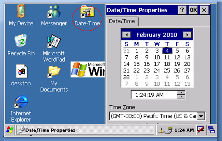
  • The following figure shows the shortcut for Date-Time control panel application on the device desktop and also it has been indicated by a red elliptical mark.
Thứ Năm, 8 tháng 9, 2011 10:39 Đọc tiếp >>

Implementing Digital Zoom Using Directshow Render on Windows CE 6.0

There are some cases wherein digital zoom is required to implement in your Directshow camera application. For example, some camera modules support a few levels of optical zoom and user have a need of more zoom level apart from the supported camera optical zoom or some camera won’t support optical zoom at all. If this is your case, then this blog post can give you some pointers to implement the digital zoom in your Directshow camera application on window CE 6.0.
Using Directshow Renderer Filter
Renders are Directshow filters used to show the video preview on the specified window. See the following MSDN link to know about video render supported in Windows CE 6.0.In the aspect of render, the video stream input to the render is called as source video and the output given by the render is called as destination video.
Digital zoom
Digital zoom is performed by cropping the required source video by playing with the pixel co-ordinates of source video, destination video and Window Coordinates. A question may rise in your mind that why we need window coordinates? Size of the object displayed on the screen should not be disturbed irrespective of the windows size changes. Also aspect ratio between the source and destination video should be maintained. Digital zoom can be achieved by cropping the required source video using SetSourcePostition() and displaying it on the preview windows with the required size using SetDestinationPostion(). The source video positions and destination video positions are calculated based on the required Zoom factor/levels.
Source-video
There are lots of ways to calculate the source and destination positions based on the zoom factor, I shall leave the choice for selecting the algorithms to find the source and destination positions to you.
Let us see the interface and the functions used to change the source and destination video positions in the video render
IBasicVideo::SetSourcePosition() and IBasicVideo::SetDestinationPosition() are the two functions involved in changing the size of source and destination video size. The IBasicVideo interface can be accessed through the video render.
Steps Involved in Accessing these Functions.
  • Since the DS filters are COM object, Load the render using CoCreateInstance().
CComPtrm_pVideoRenderer;
hr = CoCreateInstance( CLSID_VideoRenderer, NULL, CLSCTX_INPROC_SERVER,
IID_IBaseFilter, (void**) &m_pVideoRenderer );

  • Add the filter in the filter graph.
hr = m_pGraph->AddFilter(m_pVideoRenderer, TEXT(“VideoRenderer”));

  • Query the IBasicVideo interface from the video renderer.
CComPtrm_pVideoRendererBasicVideo;
hr = m_pVideoRenderer.QueryInterface( &m_pVideoRendererBasicVideo );
Now you can access the SetSourcePosition() and SetDestinationPosition() during the preview rendering. Each method is using left, top, width and height as a parameter. GetVideoSize() method is used to receive the maximum source video size for the corresponding resolution. Using these APIs you can perform digital zoom effectively.
Thứ Năm, 8 tháng 9, 2011 10:37 Đọc tiếp >>

Windows Embedded Compact 7: Silverlight Shell with ActiveSync

As usual I started looking enthusiastically on new version of WinCE named Windows Embedded Compact 7 and especially the new features of the OS. I took our reference platform Alioth (A Marvel PXA 300 based reference design) BSP to explore the features of WEC7. I took the important feature of WEC7 (ie) Silverlight Shell. Wow!!! Microsoft introduces a new GUI for WEC7. I have created the new OSDesign for my platform. I have included the “sample Home Screen Silverlight for Windows Embedded (SYSGEN_XRSHELL)” component, other necessary components and successfully build the OS image.
After downloading the image, I was bit disappointed as I couldn’t see XRShell, instead a grey blank screen appeared as shown below.

At the same time, my manager and some other Windows CE team member got success in this. Again my brain got heated up. I started collecting the OSDesign of them, compared it and I found the difference in the list of components in the OSDesign. I tried adding and removing some components in my OSDesign and finally found the culprit component. The component which is not allowing the XRShell to run is“ActiveSync”. I got a pointer to catch this issue.
I looked the source code of XRShell available in the WINCE700\public\ shell\ oak\ XRshell\ src\ CXRShell.cpp. At the same time I was looking the activities of ActiveSync during the booting. Initially I suspect that the SH_Shell API used in ActiveSync may not be implemented. I checked the CXRShell.cpp file and found that they have not implemented the API but they have given a place holder for all the SH_Shell API by filling a single API named “MissingAPI()” and they have initialize the API placeholder in CXRShell::Execute() method. CXRShell::Execute () is the method where the shell creates desktop, scenes etc…including the Initialization of SH_Shell APIs. Using this API placeholder API, XRshell allow other applications which are waiting for SH_Shell APIs to start. But our case is different.Here XRShell is blocked by ActiveSync. So the SH_ShellAPI placeholder is not an issue.
Again the next suspected activity is, ActiveSync will show notification icon on the task bar but unfortunately there is no taskbar currently implemented in XRShell. Finally I found that ActiveSync is looking for taskbar and it blocked the XRShell to launch.
Solution
I created a blank taskbar like a place holder and attach with the XRShell. Great!!! Now XRShell is launched along with the ActiveSync.

Now I have explained you – How to create a taskbar placeholder. We can easily create a taskbar from the existing source code given for Standard shell. If you explore the following source code, you can easily create a taskbar place holder.
• \Wince700\public\shell\oak\hpc\explorer\inc\taskbar.hxx
• \Wince700\public\shell\oak\hpc\explorer \taskbar.cpp
• \Wince700\public\shell\oak\hpc\explorer \main.cpp
Here is the source code I have done for creating a taskbar.
//Below macro definitions are taken from taskbar.hxx file.
#define HHTASKBARDATA 8
#define HHTASKBARCLASSNAME TEXT(“HHTaskBar”)
#define HHTASKBARID 0
#define HHTASKBARSTATE 4
//A dummy WndProc for taskbar
LRESULT CALLBACK XRshellTaskBarWndProc(HWND hwnd, UINT msg, WPARAM wParam, LPARAM lParam)
{
return 0;
}
//Referred the CTaskBar::Register() method in taskbar.cpp to create the below given code.
//Function XShellTaskBar() – Used to create a taskbar placeholder.
void XShellTaskBar(HINSTANCE hInstance)
{
RETAILMSG(1,(TEXT(“XRshell TaskBar ++\r\n”)));
HWND hwndTaskBar;
WNDCLASS wc;
wc.style = /*CS_HREDRAW | CS_VREDRAW | */CS_DBLCLKS;
wc.lpfnWndProc = (WNDPROC)XRshellTaskBarWndProc;
wc.cbClsExtra = 0;
wc.cbWndExtra = HHTASKBARDATA;
wc.hInstance = hInstance;
wc.hIcon = NULL;
wc.hCursor = 0;
wc.hbrBackground = (HBRUSH)GetStockObject(LTGRAY_BRUSH);
wc.lpszMenuName = NULL;
wc.lpszClassName = HHTASKBARCLASSNAME;
RegisterClass(&wc);
//Create a Window for the taskbar. Referred the CtaskBar::Create() in taskbar.cpp.
hwndTaskBar= CreateWindowEx(0,HHTASKBARCLASSNAME, L”", WS_POPUP, 0, 0,
10, 10, NULL, NULL, hInstance, NULL);
//After the success of window creation, Register the window as a Taskbar using RegisterTaskbar() //API. Referred the Method WINAPI CreateTaskBar()in explorer.cpp. This function calls the //CTaskbar::Register and RegisterTaskBar() API.
if( hwndTaskBar)
{
if (RegisterTaskBar(hwndTaskBar))
{
RETAILMSG(1,(TEXT(“XRShellTaskBar: RegisterTaskBar success\r\n”)));
}
else
{
RETAILMSG(1,(TEXT(“XRShellTaskBar: RegisterTaskBar failed\r\n”)));
}
}
else
{
RETAILMSG(1,(TEXT(“XRShellTaskBar: Unable to create Taskbar window\r\n”)));
}
RETAILMSG(1,(TEXT(“Xshell TaskBar –\r\n”)));
}
Taskbar placeholder is ready, Now we have to add this with XRShell. It is simple, you can add this code in CXRShell.cpp file beginning and call the XShellTaskBar() function in the CXRShell::Execute() method as shown below.
unsigned long CXRShell::Execute(int nCmdShow)
{
/*Existing Code */
…..
InitializeAPI();
XShellTaskbar(m_hInstance); //Our Black Taskbar for XRShell
CHR( ShowShell()); //This is a blocking call
…..
}
Thứ Năm, 8 tháng 9, 2011 10:36 Đọc tiếp >>